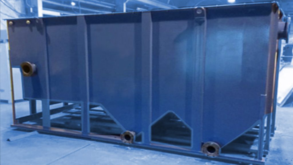
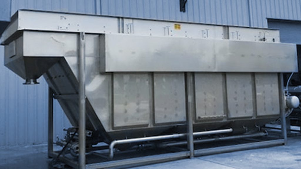
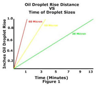
The Westlake Environmental OWS (Oil Water Separator) is designed based on Stoke’s law, which basically states the larger the oil droplet, the quicker it will rise in water, see figure 1 below. Westlake Environmental uses a special coalescing media that when placed in the flow path of oily water, the oil droplets collide with each other, grow in size and quickly rise to the water surface. This technology allows for a separator that is ½ the volume and as little as 1/5 the length of straight
gravity separators.
Stokes Law Equation: Vt = [(g)(ρw– ρo)(d²)] / [(18*μw)]
Where:
Vt = the rise rate of the oil droplet (cm/s or ft/sec)
g = acceleration due to gravity (cm/s² or ft/s²)
ρw = density of water at the design temperature (g/cm³ or lbm/ft³)
ρo = density of oil at the design temperature (g/cm³ or lbm/ft³)
d = oil droplet diameter (cm or ft)
μw = absolute viscosity of the water (g/cm•s or lbm/ft•s)
Oil Water Separation Process: The wastewater enters the OWS influent chamber via a non-clog, energy dissipating baffle that distributes the flow across the width of the coalescing pack. The separation chamber has a Westlake Media Bundle that is filled with oleophilic media that insures collision of the oil droplets, which become larger and quickly float to the water surface. As the oil layer reaches a given height on the water surface, it decants into an integral oil reservoir. The bundle is also designed such that solids will separate and settle into the sludge collection chamber. Clean water flows under a baffle and over an adjustable 304 stainless steel weir into the effluent chamber. Liquid level in the separator is determined by the height of the adjustable weir. The clean water exits the effluent chamber through an outlet flange. Sectionalized, gasketed covers are provided to allow easy access to the separator internals.
Removal Efficiencies: The model OWS will coalesce and remove non-emulsified, free and dispersed fats, oils and grease from a waste stream to produce a clean water effluent of 10 ppm or less of non-emulsified oils.
This proven design has made the Westlake Environmental OWS a preferred tool for Engineers, Contractors and End Users. Call today for more information on the Westlake Environmental Oil Water Separator.


